The distribution comb for a warm floor is not a separate part, but a whole collector assembly responsible for the correct operation of the water floor heating circuits. Our material will help owners of private houses planning to heat underfloor heating (in abbreviated form - TP) understand the device and the principle of operation of this unit, as well as get acquainted with patterns and varieties of combs.
The principle of operation of the comb floor heating
The task of underfloor heating is to warm the rooms with the entire floor surface due to the coolant circulating through pipes that are embedded in the ceiling structure. Why do you need a distribution comb TP:
- There are 2 pipelines from the heat source - supply and return, and there are 10 or more heating loops. The water from the boiler must be distributed along the contours, and not evenly, but in accordance with the need for heat.
- Floor heating is a low-temperature heating system. The coolant is heated to a maximum of 55 ° C, and the work schedule lies in the range of 35–45 ° C. It is difficult and uneconomical to provide such a mode with the help of a boiler. Therefore, combs are used for underfloor heating, regulating the temperature of the water.
With floor heating, the comb is not always needed. For 1-2 heating circuits, well-known manufacturers (for example, Oventrop, Herz Armaturen and Danfoss) offer simplified inexpensive devices with mechanical temperature regulators. For example, the Oventrop brand sells Unibox and Unidis local wall mount controls.

The basic set of the distribution unit includes the following elements:
- collector of underfloor heating for 2 or more taps with thermostatic valves and flow meters (rotameters);
- shutoff valves (ball valves);
- automatic air vents on each collector branch;
- taps or plugs for emptying;
- thermometers
- metal cabinet.
The heat-carrying lines coming from the boiler are connected to the collector, and the connections from the heating circuits of the warm floors are connected there. Thermostatic valves, manually configured or controlled automatically, are responsible for the consumption of heated water in each loop. The flow rate is shown by rotameter flasks mounted on the supply (or return) collector TP.

Reference. Collectors are made of brass, stainless steel and high-quality plastic. From the technical side, there is no difference between them, but at a price plastic will cost 15-20% cheaper than metal.
Depending on the selected operating principle of the comb and the method of adjusting the temperature of the warm water floor, the basic set is supplemented with the necessary elements. The control methods and the corresponding sets of combs in the collection we consider below.
Adjusting the amount (flow) of the coolant
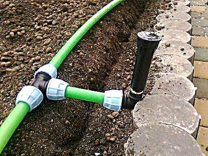
This is the easiest and cheapest way to automatically control the temperature of the floor. It consists in limiting the flow of coolant through the circuits with the help of special RTL-type thermal heads installed on collector thermostats. In this case, the connection scheme of the floor heating hinges to the comb is implemented without an additional circulation pump, as is shown in the photo:

The principle of operation of the comb is based on the ability of RTL thermal heads to focus on the return temperature of the coolant, rather than the ambient air.
On the head scale, the required return temperature is set (usually 40 ° C). When it is reached, the thermosensitive element presses on the valve stem, which closes the passage section.The amount of coolant passing through the circuit decreases, floor heating ceases. When the water in the loop cools below 40 ° C, the thermal head releases the stem again, allowing portions of hot heat transfer from the boiler to flow into the circuit.

High-quality (temperature) regulation of TP
The basis of this technique is the principle of mixing the cooled coolant coming from the underfloor heating system with hot water from the boiler. As a result, a coolant of a given temperature of 35 ... 45 ° С is supplied to the circuits. Elements of the mixing unit are added to the basic comb set:
- additional circulation pump for underfloor heating;
- a two- or three-way valve mixing hot and cooled water;
- thermal head with a remote temperature sensor;
- safety thermostat controlling the operation of the pump.
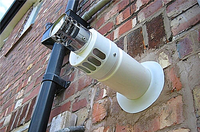
Instead of the given set of parts, you can buy a ready-made mixing unit with a pump that is joined to the comb of a warm floor. The following figure shows similar units from the Danfoss brand, designed for the thermal power of underfloor heating 9 and 13 kW:

The connection diagram of the underfloor comb with a two-way valve and a thermal head works as follows:
- At the heating stage, a two-way thermostatic valve installed on the supply line is in the open position, passing the entire coolant into the floor heating system.
- When the water temperature reaches the set value (usually 45 ° C), the liquid in the flask of the overhead temperature sensor expands and acts on the bellows of the thermal head. The latter presses on the stem of a 2-way thermostatic valve.
- Due to a further increase in temperature in the boiler line, the valve completely shuts off the flow. The coolant circulates inside the system of underfloor heating, prompted by its own pump.
- After cooling the water in the circuits for 1-2 ° C, the liquid in the sensor flask is compressed and the valve opens slightly, mixing in a portion of the hot water from the outside. So the temperature of the coolant at the outlet of the comb to the warm floors is maintained at a constant level.
- The task of the overhead safety thermostat is to stop the underfloor heating operation in an emergency when water with a temperature of more than 55 ° C enters the circuits. The thermostat shuts off the circulation pump and the servo control unit (if equipped). The working diagram of the comb with the mixing unit is shown in the figure:

Note. The bypass valve shown in the diagram serves to start the coolant in a circle through the bypass, when, due to automatic control, all heating circuits suddenly shut down and the pump has nowhere to pump water (operation with a closed valve).
3-way valve circuit
A smoother and more accurate temperature control of the coolant is provided by a mixing unit with a 3-way valve. Then the distribution comb works a little differently - mixing takes place inside the valve, and not in the supply manifold. The operation algorithm is the same as in the previous case, only the regulation is continuous and more accurate. The comb device with a three-way mixing valve is shown in the diagram:

The mixing node is controlled in the following ways:
- Manually. The handle on the valve is fixed in 1 position, the flows are mixed in constant proportions. This is a primitive and unproductive way, since the heat consumption by the underfloor heating system is a variable value.
- Automatically from a thermal head with an external temperature sensor. A mixing thermal valve with a push rod is used. When the temperature in the return manifold decreases, the thermal head releases the valve stem and the hot coolant coming from the boiler is mixed in (shown in the diagram above).
The presented method is the most expensive at the cost of components, installation and configuration, but the most effective.
Controlling heating circuits
With quality control of the coolant by temperature, its flow rate remains unchanged if additional automation is not installed. Without them, the volume of water passing through the circuit is adjusted only manually - by valves and rotameters located on the supply / return manifold. But thermal valves can be controlled automatically, if you put servos on them.

The system works like this: in rooms there are wired or wireless temperature controllers that monitor the air temperature and are connected with a single control unit (controller). He, receiving signals from room thermostats, through servos opens and closes the valves on the comb of underfloor heating. In this way, the controller can control the floor heating and the radiator system at the same time, as shown in the diagram:

In addition to temperature control, together with thermostats, the controller can do a number of interesting things:
- respond to changes in weather conditions on the street;
- pre-warm the necessary rooms to a given time;
- turn off heating underfloor heating in unused rooms;
- remotely controlled via GSM or Internet.
The use of servos and automation means not only increases the comfort for living, but also allows you to save 15-20% of the money spent on energy and thus reduce the price of heating a private house.
DIY comb for underfloor heating
Since the distribution comb for underfloor heating assembly costs a lot of money, there are a couple of ways to save money by making a supply and return manifold with your own hands:
- assemble a knot of brass or plastic tees designed for heating.
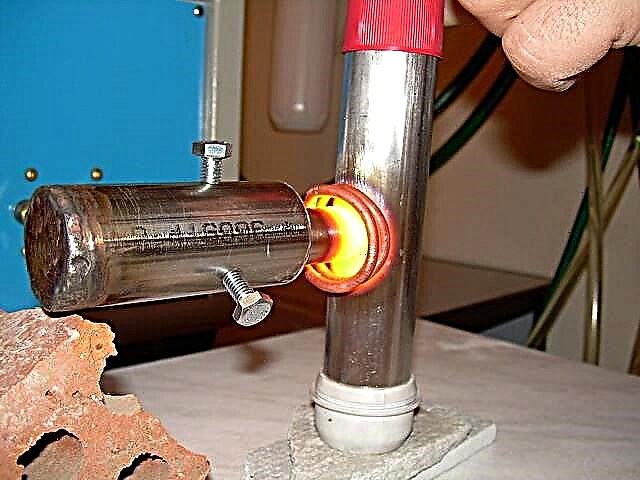
- solder a comb made of polypropylene independently.

In both cases, you will have to buy thermostatic valves and other elements according to the selected control scheme. Tees are connected on the thread, and polypropylene fittings - by welding (soldering). The number of connections is quite large, each joint must be done reliably so that subsequently there are no leaks. In the manufacture of combs from polypropylene, the heating time should be maintained and the parts connected as quickly as possible.
The main drawback of combs for self-made underfloor heating is the difficulty of pre-setting and adjustment without flow meters. The flow rate of the coolant will have to be determined at random, even when the lengths of the pipes in the circuits are the same, since the heat losses in the rooms are different.

Conclusions and recommendations
Judging by the reviews on the forums, homeowners are familiar with combs equipped with a mixing unit and pump. It is noteworthy that not all masters are aware of the existence of RTL-type thermal heads. And they can significantly reduce the price of the heat-insulated comb installed in a small or medium-sized country house (up to 250 m²). Hence the recommendations:
- If possible, use a factory or homemade comb with RTL thermal heads, then you do not have to buy a circulation pump and valves. The main condition is the length of the contours of not more than 60 m.
- If the number of loops reaches 10 or more, and the supply line from the boiler is quite long, choose a more powerful main pump. You can put the unit Grundfos Alfa-2 15-60 with Autoadapt function to save electricity.
- For circuit lengths of up to 100 m, a house area of over 250 m² and a complex heating system, use a comb with a two- or three-way valve (quality control).
- If possible, equip the comb and underfloor heating system with automation equipment. To do this, it is recommended to consult a specialist in this field.
Note. Designers and manufacturers of components for underfloor heating categorically do not recommend making the length of the pipe in one loop more than 100 m (Ø16 mm).