The result of the technical situation, when the stator windings of the motor consume more current than the set parametric values, is excess heat. This factor causes a decrease in the quality of motor insulation. Equipment fails.
The reaction time of thermal overload relays is usually not enough to provide effective protection against excess heat generated by high current. In such cases, only the phase monitoring relay is seen as an effective protective device.
General Instrument Information
The functionality of electrical appliances of this type is much wider than just protection against overheating and short circuit.
In practice, the effective properties of the relay for selecting overloaded phases have been noted, which ultimately provide comprehensive protection.

One of the many design options in the production of phase relays. However, despite the variety of cases and circuit configurations, the functionality of the devices is the same
Thanks to phase monitoring devices, the following benefits are achieved:
- extended engine life;
- reducing costly repairs or replacing a motor;
- reduced downtime due to engine defects;
- reduced risk of electric shock.
In addition, the device provides reliable protection against fire and short-circuit of the motor windings.
Typical safety relays
There are two main types of protective devices intended for use as part of three-phase systems - current measurement and voltage relays.
Pros of using devices
The advantage of current protection relays with respect to voltage monitoring relays is obvious. This type of instrument operates independently of the influence of EMF (electromotive force), which invariably accompanies a phase failure during engine overloads.
In addition, devices operating on the principle of measuring current are able to determine the abnormal behavior of the motor. Monitoring is possible either on the line side in the branch circuit, or on the load side where the relay is installed.

This is one of the models of the voltage monitoring relay. Such devices can be used not only for industrial needs, but also for private households
Instruments that control the process by the principle of measuring voltage are limited to detecting abnormal operating conditions only on the side of the line where the device is connected.
However, voltage sensitive devices also have an important advantage. It lies in the ability of devices of this type to detect an abnormal condition that is independent of the state of the engine.
For example, a relay type that is sensitive to changes in current detects an abnormal phase state only directly during engine operation. But the voltage measuring device provides protection immediately before starting the motor.
Also among the advantages of voltage measuring devices are simple installation and lower price.
This type of protection device:
- does not need additional current transformers;
- applied regardless of system load.
And for it to work, you just need to connect the voltage.
Phase Failure Detection
A phase failure is quite possible due to the failure of a fuse in one of the parts of the power distribution system. A mechanical failure of the switching equipment or a break in one of the power lines also provokes a phase failure.

Motor protection, organized through a monitoring relay. This method allows more efficient operation of the motors, without fear of their quick failure
A single-phase three-phase motor draws the required current from the remaining two lines. Attempting to start it in single-phase mode will block the rotor and the engine will not start.
The reaction time per thermal overload unit may be too long to provide effective protection against excessive heat. If a thermal relay is not installed to protect against it, then when a failure occurs due to overheating that appears in the motor windings.
Protection of a three-phase motor from a phase failure factor is difficult because an underloaded three-phase motor operating on one of the three phases generates a voltage called regenerated (reverse emf).
It is formed inside a tattered winding and is almost equal to the value of the lost input voltage. Therefore, voltage measurement relays that control only its value in such situations do not provide complete protection against the phase failure factor.

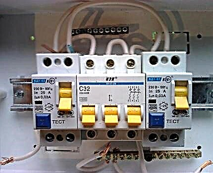
The connection diagram of the phase and voltage control device in the control circuit of a three-phase motor. This is a classic schematic version used in practice everywhere.
A higher degree of protection can be obtained using a device that can detect phase angle displacement, usually accompanying phase failure. Under normal conditions, the three-phase voltage is 120 degrees in phase relative to each other. Failure will cause the angle to shift from normal to 120 degrees.
Phase reverse detection
Phase reversal can occur:
- Maintenance is being carried out on motor equipment.
- The electricity distribution system has been amended.
- When power recovery leads to a different phase sequence that was before the power outage.
The detection of a phase reversal is important if a reverse engine can damage the driven mechanism or, even worse, cause physical harm to maintenance personnel.

Among other things, the use of protective relays is to ensure the safety of working personnel: 1 - dangling phase; 2 - step voltage
The rules of operation of electric networks require the use of protection against possible phase reversal on all equipment, including vehicles for transporting personnel (escalators, elevators, etc.).
Voltage imbalance detection
An imbalance is usually manifested if the incoming line voltage supplied by the electricity company has different levels. An imbalance can occur when single-phase loads of lighting, electrical outputs, single-phase motors and other equipment are connected in separate phases and are not distributed in a balanced manner.
In any of these cases, a current imbalance forms in the system, which reduces efficiency and shortens the life of the motor.
An unbalanced or insufficient voltage applied to a three-phase motor leads to an imbalance in the current in the stator windings equal to the multiple value of the unbalance of the interphase voltages. This moment, in turn, is accompanied by an increase in heating, which is the main reason for the rapid destruction of the motor insulation.
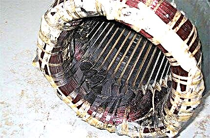
The burned-out winding of the motor stator is a common occurrence, where the introduction of relay control into the control circuit was not provided.
Based on all the technical and technological factors described, it becomes obvious the importance of using this type of relay and not only for cases of operation of electric motors, but also for generators, transformers and other electrical equipment.
How to connect a control device?
The design of the relays that control the phases, with all the extensive product range available, has a unified housing.
Product structural elements
Terminal blocks for connecting electrical conductors, as a rule, are displayed on the front of the case, which is convenient for installation work.
The device itself is made for installation on a DIN rail or simply on a flat plane. The terminal strip interface is usually a standard reliable clamp designed for mounting copper (aluminum) conductors with a cross-section up to 2.5 mm2.
The front panel of the device contains a regulator / adjusters, as well as a light control indication. The latter shows the presence / absence of supply voltage, as well as the state of the actuator.

Potentiometer settings may include an alarm indicator, a connected load indicator, a mode selection potentiometer, an asymmetry level adjustment, a voltage drop regulator, a time delay adjustment potentiometer
Three-phase voltage is connected at the operating terminals of the device, indicated by the corresponding technical symbols (L1, L2, L3). The installation of a neutral conductor on such devices is usually not provided, but this moment is specifically determined by the execution of the relay - the type of model.
To connect to control circuits, a second interface group is used, usually consisting of at least 6 working terminals. One pair of the contact group of the relay commutates the coil circuit of the magnetic starter, and through the second, the control circuit of the electrical equipment.
Everything is quite simple. However, each individual relay model may have its own connection features. Therefore, applying the device in practice, one should always be guided by the accompanying documentation.
Fixture setup steps
Again, depending on the version, the design of the product can be equipped with different circuit options for setting and adjusting. There are simple models that provide constructive output to the control panel of one or two potentiometers. And there are devices with advanced settings.

Microswitch settings: 1 - microswitch unit; 2, 3, 4 - installation options for operating voltages; 5, 6, 7, 8 - options for setting asymmetry / symmetry functions
Among these advanced tuning elements, block microswitches are often found located directly on the printed circuit board under the device body or in a special openable niche. By setting each of them in one position or another, the required configuration is created.
The setting usually boils down to setting the protection values by rotating the potentiometers or by positioning the microswitches. For example, to monitor the state of contacts, the sensitivity level of the voltage difference (ΔU) is usually set to 0.5 V.
If it is necessary to control the power supply lines of the load, the voltage difference sensitivity regulator (ΔU) is adjusted to such a boundary position where the transition point from the working signal to the emergency one is noted with a small tolerance towards the nominal value.
As a rule, all the nuances of the instrument settings are clearly described by the accompanying documentation.
Marking Phase Control
Classical instruments are simply labeled. An alphanumeric sequence is applied on the front or side panel of the case, or the designation is indicated in the passport.

An option for marking one of the most popular devices of domestic production. The designation is made on the front panel, but there are also variations with placement on the sidewalls
So, a Russian-made device for connecting without a neutral wire is marked:
EL-13M-15 AC400V
where: EL-13M-15 - the name of the series, AC400V - permissible AC voltage.
Samples of imported products are marked slightly different.
For example, a PAHA series relay is abbreviated as follows:
PAHA B400 A A 3 C
The decoding is approximately the following:
- PAHA is the name of the series.
- B400 - standard voltage 400 V or connected from a transformer.
- A - adjustment by potentiometers and microswitches.
- A (E) - type of enclosure for mounting on a DIN rail or in a special connector.
- 3 - case size of 35 mm.
- C is the end of the code marking.
On some models, another value may be added before paragraph 2. For example, "400-1" or "400-2", and the sequence of the others does not change.
This is how phase control devices are marked, endowed with an additional power interface for an external source. In the first case, the supply voltage is 10-100 V, in the second 100-1000 V.
The following article, which we highly recommend reading, will familiarize you with the principle of operation, design features and the purpose of the load switch.
The video is dedicated to describing and reviewing a single product from EKF. However, almost all manufactured phase monitoring devices operate on the same principle:
With all the variety of devices on the market, it is difficult to determine any standard for labeling. If foreign manufacturers label according to one canon, then domestic ones according to others. Nevertheless, it is always possible to refer to reference data if an exact interpretation of the characteristics is required.
Do you want to share your own experience in the selection and installation of a voltage relay designed for phase monitoring? Do you have useful information that is useful to site visitors? Please write comments in the block below, post pictures on the topic, ask questions.